
Blog By: Leo Xu - Matrium Technologies
In Network Testing, Customers often ask us “How can we make our applications experience real-world network conditions?” while they are performing QA in a sandbox environment.
What follows is a technical deep dive on introducing a variety of network conditions in a lab environment.
When attempting to understand the actual performance of an application in a real-world WAN situation, factors such as Packet Drop, Increased Latency and Jitter are introduced to ensure the stability and performance of the application. Recently, I encountered a very interesting use case for traffic impairment between 2 VMs in ESXi. At first glance, it may seem an impossible challenge to overcome, but by following the process below you'll see how it can be achieved.
The Scenario:
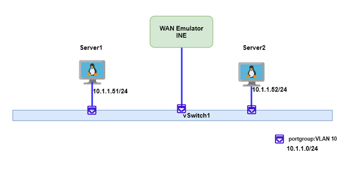
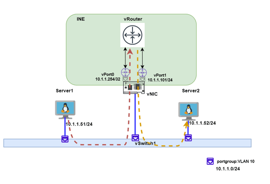
The diagram below shows the simplified topology. Server1 and Server2 are both VMs and due to certain reasons, both VMs should be in the same subnet/VLAN, if packets are dropped or increased latency happens between Server1 and Server2, then the systems overall performance should be measured.
So how can we achieve this since two servers can talk directly and no routing is required at all?
In our case, our partner iTrinegy has virtualised their WAN emulator for ESXi and Openstack. The routing function is so flexible that the INE can emulate almost all the WAN topologies. To further tackle this problem, a few more steps are still required.
The Solution:
As many readers would be aware, it is a layer 2 man-in-the-middle attack. Except, in this case, we can fully control Server1 and Server2, so adding a static arp entry would point the traffic into the middle man.
With the MITM (man-in-the-middle) being formed, the traffic between Server1 and Server2 will go through the INE. The remaining steps involved are to configure the INE to achieve routing and impairment.
Thankfully the INE provides a very powerful routing function. If there is only Server1 and Server2, then a simple arrow Object could resolve this problem.
A virtual topology with a simple arrow in INE can be created.
On the single vNIC of INE, 2 IP address will be added as sub-ports.
vPort0 10.1.1.254/32
vPort1 10.1.1.101/24
A little explanation for this configuration. You might notice this configuration looks abnormal because the address is overlapping. Network engineers might also think /32 is for loopback and that the /32 interface address is not right in a router since it cannot connect any devices. You need to keep in mind that the INE is not a traditional router, these rules are not applied in INE.
In above the topology, vPort0 10.1.1.254/32 will act as the middle man, it will receive traffic from Server1 and Server2, the traffic then sends to vPort1. vPort1 is a normal Layer 3 IP address and it will try to forward traffic to Server1 or Server2.
The reason for the /32 address is that it is a sub-optimal routing case. INE will not forward the traffic if INE thinks source and destination are in the same subnet. Since the sub-optimal case will cause the routing loop, the INE can consider this to be understood.
Let's say 10.1.1.254 mac address is 00:10:0a:01:01:fe
in Server1, point Server2 traffic to vPort0
arp -s 10.1.1.52 00:10:0a:01:01:fe
in Server2, point Server1 traffic to vPort0
arp -s 10.1.1.51 00:10:0a:01:01:fe
INE simple arrow properties.
It is a straightforward configuration. Everything received in vPort0 will be forwarded to vPort1.
If there are just 2 servers, this would be enough but when 10 servers are in the same subnet, part of the traffic flow between servers should be impaired. Therefore, the simple arrow method might not be very suitable.
The following topology is still using 2 servers as an example while introducing a centralised router to perform the routing function.
Here is a more complex topology with a more scalable solution:
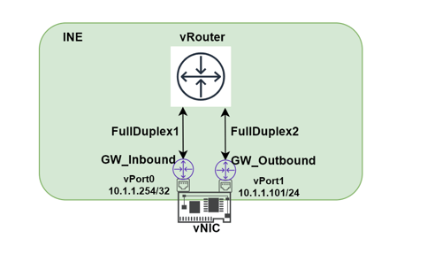
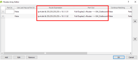
A few nodes are introduced, vRouter will be responsible for centralised routing. GW_Inbound will be acting as the middleman to receive all the traffic then forwarding to vRouter. GW_Outbound will be responsible for forwarding the traffic to the real destination. vRouter will make the final routing decision and the expression routing function is used to manipulate the traffic.
Here are a few configuration details.
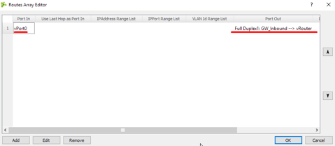
GW_Inbound
vRouter:
when GW_Outbound receives the traffic from vRouter, it will be normal layer 2 forwarding.
The detailed traffic would be like the following diagram:
Now let's add latency impairment random drop 10% and 5ms latency in the line between vRouter and GW_Outbound.
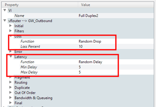
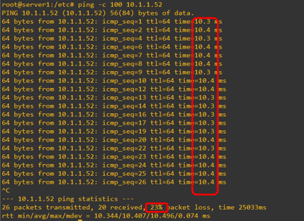
Again, due to the traffic flow inside INE is always vPort0 -> vRouter -> vPort1, so impairment is applied in both directions. Doubling of the latency value is expected.
This doesn’t seem like much of a change for the current Server1 and Server 2 scenario, but it is capable of a much more complex architecture than the simple arrow topology. The following example shows where the centralised routing feature would easily achieve this.
#impariment requirement

server1 and server2    latency 10ms
server1 and server3    latency 20ms
server2 and server3    latency 30ms
so inside INE, the following topology could address this.
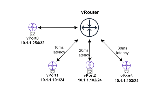
In vRouter, we simply manipulate the traffic to the link by the expression routing, then it is all done!
For further information on Network Impairment, please contact Matrium Technologies on:
P: 1300 889 888
E: info@matrium.com.au